


Blog
- Pellet machine performance depends on controlled feeding, conditioning, compression, and mechanical stability, with production commonly reaching 1,500–3,000 kg/h
Poultry feed pellet machine troubleshooting combines process monitoring, die selection, roller adjustment, and maintenance to protect continuous chicken-feed production
Chicken feed pellet machine performance responds directly to moisture, steam, compression geometry, pellet sizing, and component condition during production
Mechanical diagnosis covers six practical fault areas, helping operators identify blockage, overload, fines, dimensional variation, and vibration without unnecessary replacement
- Integrated equipment design connects feeding, conditioning, forming, cutting, and maintenance, creating a measurable production workflow for commercial poultry feed plants
Get professional poultry farm construction guidance, equipment selection solutions, and the latest price lists, whatsApp to +8618830120193, click to learn more:
Diagnose The Machine By Failure Signature
Pellet machine troubleshooting should begin with measurable operating behavior rather than component replacement.
In poultry feed production, the key variables are material flow, compression resistance, mechanical condition, and thermal conditioning.
Poultry feed pellet machine diagnosis can isolate faults before maintenance costs escalate, while chicken feed pellet machine monitoring benefits from fixed operating records.
For engineering teams, record operating data at fixed intervals.
A practical monitoring cycle is 30 minutes, while a fault trend should be reviewed across at least 8 operating hours.
Chicken feed pellet machine operators can compare feed changes, machine adjustments, and maintenance actions against that baseline.
Six-Fault Diagnostic Data Matrix
Data is for reference only.Swipe horizontally to view full table.
These reference values should be treated as engineering starting points rather than universal production limits.
Actual performance depends on formulation, die configuration, raw-material properties, and machine model.
Poultry feed pellet machine selection should therefore match actual production requirements instead of relying on generic capacity claims.
Fix #1 — Stabilize Feeding Before Increasing Compression
The feeder determines how much material enters the compression chamber per unit of time.
When the material stream fluctuates, roller loading changes continuously and operators may incorrectly attribute unstable production to the die.
Use a controlled adjustment sequence: establish a steady feed stream, observe motor response, then change the feeder setting in small increments.
A 5% feeder-speed adjustment is generally more controllable than making a large immediate correction.
For poultry feed equipment, a variable-frequency feeder can improve process control because feed rate can be matched to motor response instead of relying entirely on manual gate adjustment.
Poultry feed pellet machine systems benefit particularly when formulas change during the same production shift.
Feeding-System Engineering Parameters
Data is for reference only.Swipe horizontally to view full table.
A controlled feeding system is also a practical equipment advantage for poultry producers because controlled material delivery supports capacity stability and operator control.
Our chicken feed pellet machine configuration can integrate controlled feeding with the main compression unit for continuous production.
Fix #2 — Manage Conditioning As A Thermal Process
Pellet quality is strongly affected before material reaches the die.
Steam conditioning changes starch behavior and moisture distribution, allowing mash to pass through the compression zone with more consistent forming characteristics.
For poultry feed, a typical conditioning residence period can be designed around 45–90 seconds, while conditioning temperature may operate around 75–85°C, depending on formulation and process design.
Poultry feed pellet machine systems therefore require coordinated steam delivery rather than simply increasing steam volume.
The conditioner must deliver uniform heat and moisture throughout the feed stream.
Our chicken feed pellet machine systems can integrate conditioning equipment with the pellet mill so operators can control preparation before compression.
Conditioning System Data Reference
Data is for reference only.Swipe horizontally to view full table.
These values are process references and should be validated against feed formulation and machine configuration.
Poultry feed pellet machine conditioning performance should be commissioned according to actual material behavior.
Fix #3 — Select The Die As A Compression Component
The die should be treated as an engineered forming component rather than a consumable selected only by pellet diameter.
Effective hole length, hole geometry, material condition, and formulation all influence resistance inside the compression channel.
For poultry applications, published references commonly place die compression ratios around 1:8–1:12 depending on feed type and pellet specification.
Chicken feed pellet machine buyers should therefore evaluate formulation, target pellet diameter, capacity, and electrical configuration before selecting a die.
A practical equipment supplier should match die specifications to the complete production process rather than offering one fixed die for every chicken-feed application.
Die Engineering Specification Table
Data is for reference only.Swipe horizontally to view full table.
Die compression ratio is calculated from effective hole length and hole diameter.
Poultry feed pellet machine die selection should be finalized according to formulation and target production conditions.
Fix #4 — Correct Roller-To-Die Geometry
When pellets become inconsistent, inspect the mechanical relationship between the roller and die before changing the formulation.
Incorrect roller positioning can reduce material capture, disturb compression, and accelerate component wear.
Use a calibrated feeler gauge during adjustment.
For ring-die systems, an engineering reference is approximately 0.10–0.30 mm for roller-to-die working clearance.
Chicken feed pellet machine maintenance should keep roller positioning even around the die.
Unequal positioning can create localized loading, resulting in inconsistent forming and unnecessary mechanical stress.
A properly engineered poultry feed pellet machine should provide accessible adjustment points so maintenance personnel can perform this operation accurately.
Roller And Die Mechanical Data
Data is for reference only.Swipe horizontally to view full table.
Correct roller and die geometry directly influences compression stability.
Poultry feed pellet machine die material and surface hardness are also important when equipment operates continuously under abrasive feed conditions.
Fix #5 — Treat Vibration As A Mechanical Diagnostic Signal
Vibration should be interpreted through component condition rather than noise level alone.
Bearing wear, shaft imbalance, coupling alignment, loose fasteners, and die installation errors can all produce characteristic mechanical responses.
During preventive maintenance, record vibration at identical measurement points.
A useful monitoring interval is 500 operating hours, while bearing lubrication intervals may be established around 250 operating hours, subject to bearing type and manufacturer instructions.
Our chicken feed pellet machine systems can be configured with service-accessible transmission components, making routine inspection easier for feed mills operating multiple shifts.
This approach reduces dependence on emergency maintenance and supports predictable production scheduling.
Mechanical Maintenance Data & Six-Fix Checklist
Data is for reference only.Swipe horizontally to view full table.
The six troubleshooting actions can therefore be organized into one engineering workflow: stabilize feeding, control conditioning, match the die, correct roller geometry, inspect mechanical vibration, and document maintenance data.
For poultry equipment buyers, machine quality becomes commercially important because reliable operation depends on adjustable process control, accessible maintenance points, replaceable wear components, and engineering support.
Our poultry feed pellet machine approach connects feeding, conditioning, compression, cutting, transmission, and maintenance into one production system.
For chicken feed pellet machine projects, integrated engineering can reduce troubleshooting complexity and create a more repeatable production workflow.
Frequently Asked Questions
Q1: What should be checked first when a pellet machine loses production capacity?
Start with material feeding, motor response, and die condition rather than replacing components immediately.
A 30-minute operating record can provide useful evidence for identifying process fluctuations.
Q2: How should a poultry feed pellet machine handle unstable pellet durability?
Check conditioning consistency, die configuration, roller geometry, and formulation together.
Maintaining suitable process conditions can support a PDI around 88% or above, depending on feed formulation and equipment configuration.
Q3: When should a chicken feed pellet machine receive preventive mechanical inspection?
Establish inspection according to operating hours, component design, and manufacturer recommendations.
A maintenance program using 250-hour and 500-hour checkpoints can provide a practical framework for routine equipment monitoring.
Taiyu (HK) Group - One Of China Toppest Pellet Machine Manufacturer
Pellet machine integrates controlled feeding, conditioning, compression, cutting, and transmission, with configurable production capacity reaching 3,000 kg/h for poultry feed applications
Global factory-direct supply covers poultry equipment, engineering configuration, production-line integration, installation guidance, and technical commissioning for international projects
Turn-key engineering combines feed preparation, grinding, mixing, conditioning, pelleting, cooling, screening, and conveying into coordinated production systems
Project support covers equipment selection, process layout, electrical configuration, spare parts planning, operator training, and commissioning documentation
Poultry production projects can be configured around formulation, capacity requirements, pellet specifications, workshop dimensions, and local operating standards
Contact Us To Received Your Customized Poultry Farm Plan
Headquarters And Branchs
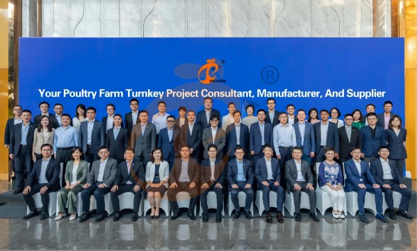
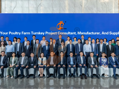
Hong Kong Headquarter Management Team
Hong Kong Headquarter Taiyu Industrial Group CO., LTD
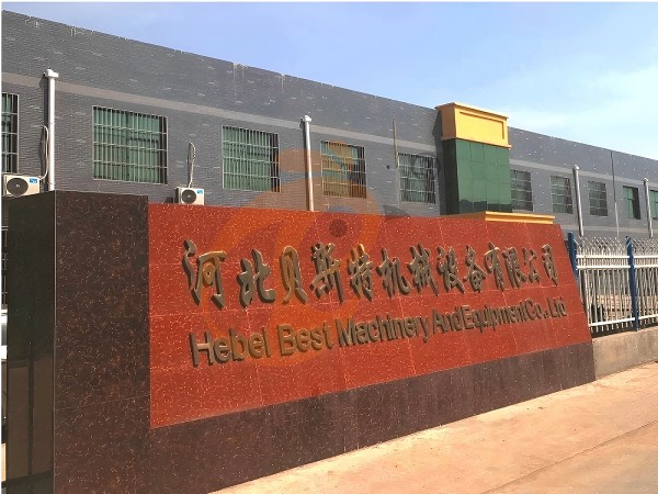
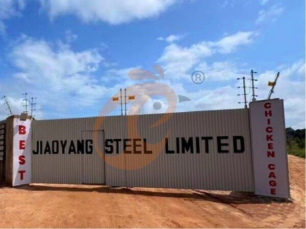
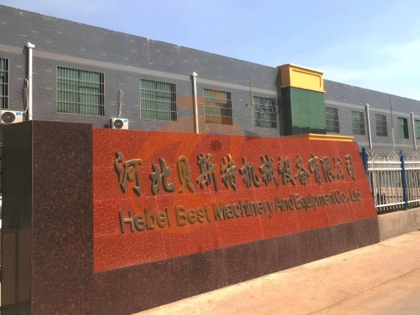
China Hebei Best Machinery And Equipment CO., LTD
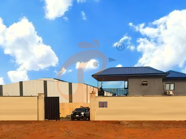
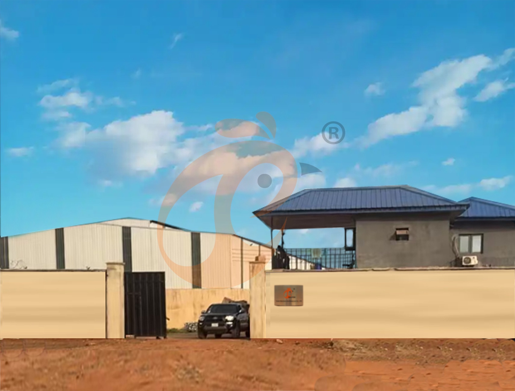
Nigeria Vanke Machinery And Equipment CO., LTD
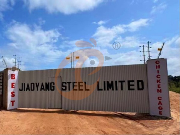
Tanzania Best Machinery And Equipment CO., LTD
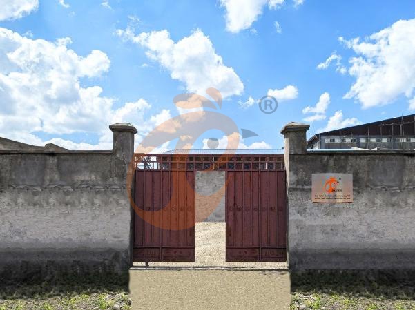
Ethiopia Best Hebei Machinery Manufacturing PLC

Reception /24 WhatsApp NO. : +8618830120193
FAQ
What Pellet Quality Indicators Are Required From Pellet Machine In Poultry Chicken Feed Manufacturing?
Hardness level is controlled at 3–5 kg/cm² for optimal bird consumption efficiency.
Fines content is kept below 8% to ensure uniform feed intake performance.
What Die Specification Standards Are Used In Pellet Machine For Poultry Chicken Feed Production?
Compression ratio ranges from 1:6 to 1:8 to ensure proper pellet density structure.
Die material hardness reaches HRC 50–55 for extended wear resistance under continuous operation.
What Roller System Parameters Are Required In Pellet Machine For Poultry Chicken Feed Processing?
Roller gap is adjusted between 0.1–0.3 mm to control pellet density formation.
Roller lifespan typically reaches 600–900 operating hours under standard feed production conditions.
Message
Products recommended
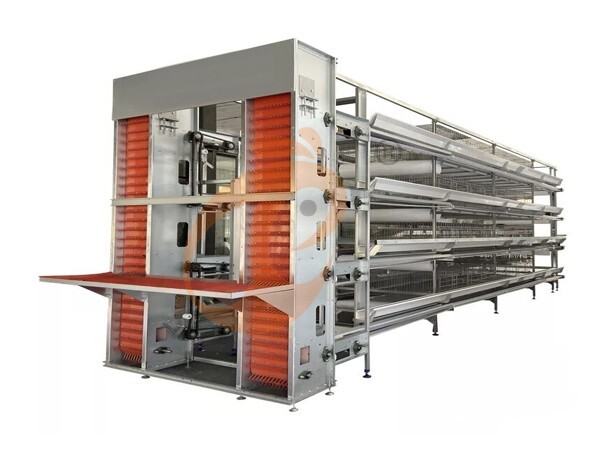
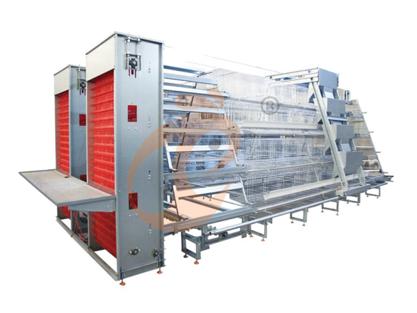
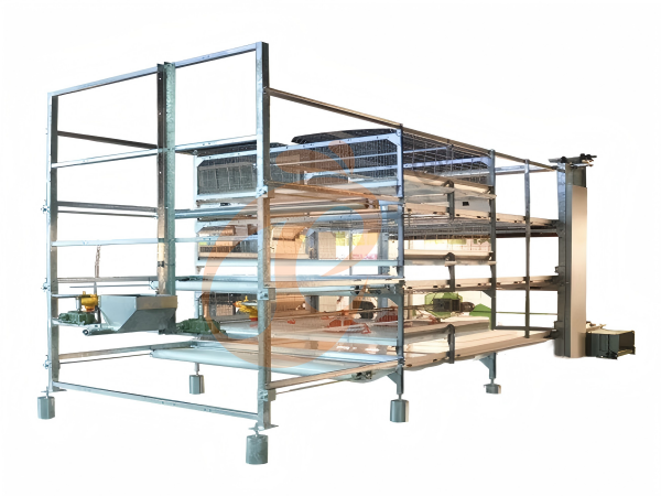
 >30,000 Pullets Automatic H Type Battery Cage1. More than 30,000 pullets a house, choose it.
2. It is designed to rearing older than 1 day old pullets to 12 to 16 weeks old chicken starting laying eggs.
3. Its lifespan is more than 25 years.
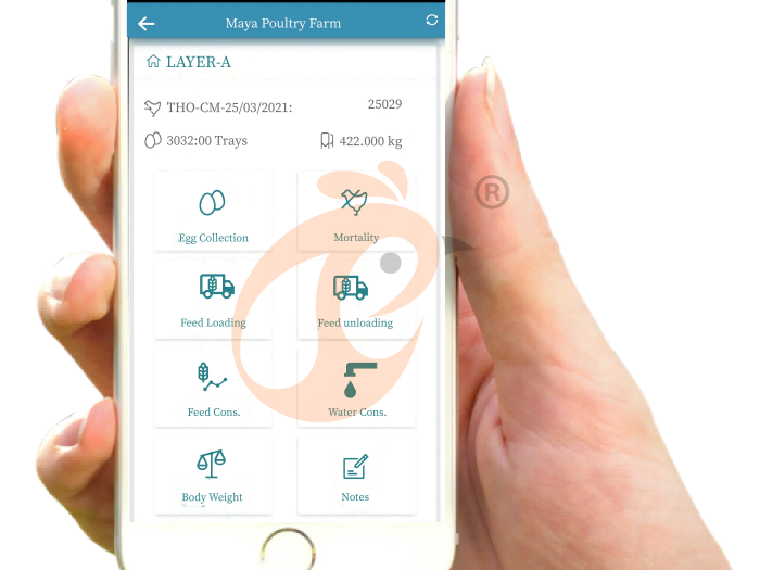
4. Its structure are Vcloud artificial intelligent fusion, electric control cabinet, automatic equipment of drinking, feeding, manure clean, manual harvesting.
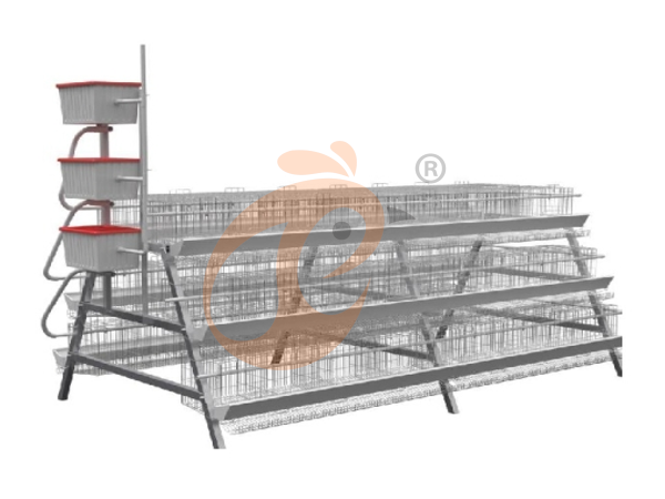
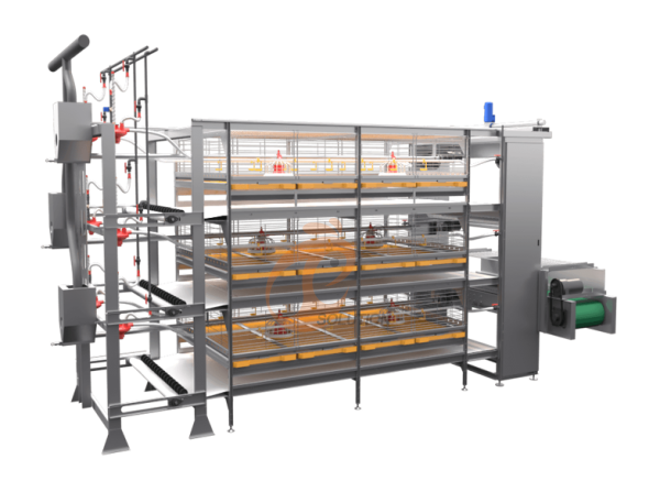
5. Our 24 hour online reception What’sApp NO. is +8618830120193 <30,000 Pullets Automatic A Type Battery Cage1. 10,000 to 30,000 pullets a house, choose it.
2. It is designed to rearing older than 1 day old pullets to 12 to 16 weeks old chicken starting laying eggs.
3. Its lifespan is more than 25 years.
4. Its structure are Vcloud artificial intelligent fusion, electric control cabinet, automatic equipment of drinking, feeding, manure clean, manual harvesting.
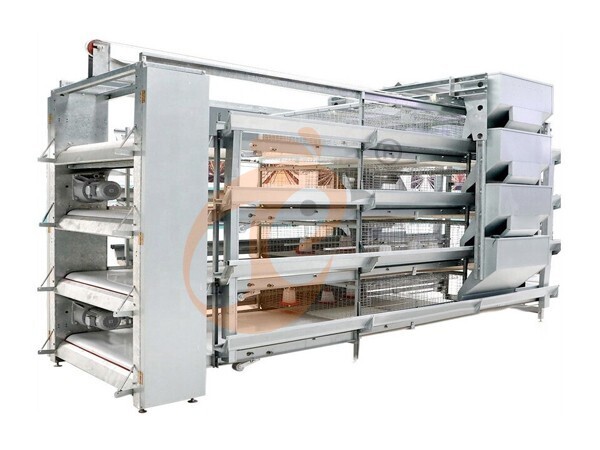
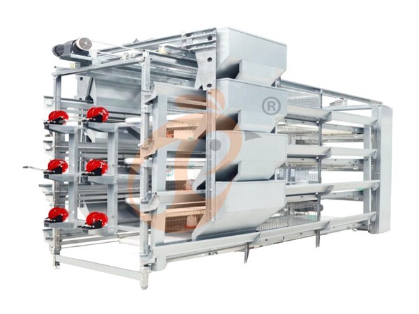
5. Our 24 hour online reception What’sApp NO. is +86 18830120193. >30,000 Broilers Semi-Automatic Harvest H Type Battery Cage1. More than 30,000 broilers a house, choose it.
2. It is designed to rearing 1 to 45 day old adult broiler ready for market.
3. Its lifespan is more than 20 years.
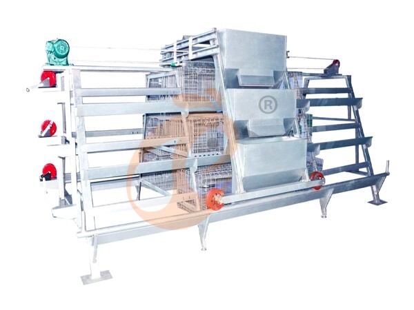
4. Our 24 hour online reception What’sApp NO. is +8618830120193, +234 8111199996. >30,000 Broilers Manual Harvest H Type Battery Cage1. More than 30,000 broilers a house, choose it.
2. It is designed to rearing 1 to 45 day old adult broiler ready for market.
3. Its lifespan is more than 20 years.
4. Its structure are Vcloud artificial intelligent fusion, electric control cabinet, automatic equipment of drinking, feeding and manure clean, manual harvesting.
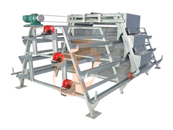
5. Our 24 hour online reception What’sApp NO. is +8618830120193, +234 8111199996. <30,000 Broilers Manual Harvest A Type Battery Cage1. Less 30,000 broilers a house, choose it.
2. It is designed to rearing 1 to 45 day old adult broiler ready for market.
3. Its lifespan is more than 20 years.
4. Its structure are Vcloud artificial intelligent fusion, electric control cabinet, automatic equipment of drinking, feeding and manure clean, manual harvesting.
5. Our 24 hour online reception What’sApp NO. is +8618830120193, +234 8111199996. HK Headquarter Offers EU-standard Poultry Farm Solutions, Manufacture Poultry Farm Equipment1. Continuous communication with the EU and the US
2. China, Nigeria, Ethiopia, Tanzania branch companies and factories
3. The products’ quality is customized for local poultry farms
4. Poultry cage and poultry farm equipment stock for sale
5. 24 online reception Whatsapp NO. : +8618830120193,contact us to get full information China Branch Offer Poultry Farm Business Plan, Manufacture Poultry Farm Equipment1. Address: Flat/RM 2416, 24/F, Runxing Building, Youyi Nan Street, Shijiazhuang City, Hebei Province, China
2. Poultry cage and poultry farm equipment factory and stock for sale
3. Customized for local poultry farms
4. Quality and design are based on Euro
5. 24 online reception Whatsapp NO. : +8618830120193 Nigeria Branch Offer Poultry Farm Business Plan, Manufacture Poultry Farm Equipment1. Address: After Sinoma Office, 200 Meters Near Danco Filling Station, Lagos/Ibadan Expressway, Lagos State, Nigeria
2. Poultry cage and poultry farm equipment factory and stock for sale
3. Customized for Nigerian poultry farms
4. Quality and design are based on Euro
5. 24 online reception Whatsapp NO. : +8618830120193 Ethiopia Branch Offer Poultry Farm Business Plan, Manufacture Poultry Farm Equipment1. Address: Gelan Gura, Akaki-kaliti Sub City, Addis Ababa, Ethiopia
2. Poultry cage and poultry farm equipment stock for sale
3. Customized for Ethiopian poultry farms
4. Quality and design are based on Euro
5. 24 online reception Whatsapp NO. : +8618830120193, contact us to get price list Tanzania Branch Offer Poultry Farm Business Plan, Manufacture Poultry Farm Equipment1. Address: No.8, Sova Road, Msufini, Mlandizi, Kibaha, Pwani, Tanzania
2. Poultry cage and poultry farm equipment factory and stock for sale
3. Customized for Tanzanian poultry farms
4. Quality and design are based on Euro
5. 24 online reception Whatsapp NO. : +8618830120193



Contact