

Blog
Poultry manure system installation integrates mechanical transmission, belt dynamics, and structural alignment engineering to achieve controlled waste discharge performance across multi-tier cage farms.
Automated manure belt equipment reduces manual scraping frequency from multiple cycles per day to programmable discharge intervals based on controller logic.
High precision scraper assembly ensures residual manure thickness is controlled within millimeter-scale limits for hygienic poultry housing environments.
Conveyor-based manure export system enables continuous transfer distances exceeding 20 meters without intermediate manual handling.
Integrated poultry manure engineering system stabilizes ammonia emission patterns by controlling decomposition time window under 24-hour cycle thresholds.
Get professional poultry farm construction guidance, equipment selection solutions, and the latest price lists, whatsApp to +8618830120193, click to learn more:

System Composition And Product Structure
A complete manure system consists of multiple integrated subsystems.
Component selection directly determines load stability and transmission efficiency.
Data is for reference only.Swipe horizontally to view full table.
Pre Installation Measurement And Layout
Installation accuracy depends on spatial calibration between cage rows and drive axes.
Data is for reference only.Swipe horizontally to view full table.
Installation Tools And Technical Requirements
Tool precision directly affects structural assembly tolerance and motor alignment accuracy.
Data is for reference only.Swipe horizontally to view full table.
Frame Installation And Alignment
Frame structure determines load transmission path and vibration absorption efficiency.
Data is for reference only.Swipe horizontally to view full table.
Manure Belt Installation And Tensioning
Belt system performance depends on controlled elastic deformation range and friction coefficient stability.
Data is for reference only.Swipe horizontally to view full table.
Drive System Installation
Drive system calibration ensures synchronization between torque output and belt velocity curve.
Data is for reference only.Swipe horizontally to view full table.
Scraper And Cleaning Mechanism Setup
Scraper geometry determines cleaning efficiency per rotation cycle and residue thickness control.
Data is for reference only.Swipe horizontally to view full table.
Conveyor System Installation
Conveyor system design determines maximum discharge distance and hourly transport throughput.
Data is for reference only.Swipe horizontally to view full table.
Electrical Control System Installation
Electrical architecture governs load distribution, safety cutoff response time, and automation cycles.
Data is for reference only.Swipe horizontally to view full table.
System Testing And Commissioning
Testing evaluates mechanical synchronization, electrical response, and load endurance performance.
Data is for reference only.Swipe horizontally to view full table.
Belt Deviation And Correction
Deviation correction requires multi-point adjustment across tension and roller geometry axes.
Data is for reference only.Swipe horizontally to view full table.
Low Transport Efficiency
Transport inefficiency is associated with torque loss, material buildup, and speed decay factors.
Data is for reference only.Swipe horizontally to view full table.
Accelerated Wear Of Components
Wear analysis focuses on material fatigue rate and mechanical abrasion thresholds.
Data is for reference only.Swipe horizontally to view full table.
Scientific Explanation Ammonia Control Mechanism
Ammonia concentration is directly related to manure residence time and microbial activity rate under controlled temperature conditions.
Data is for reference only.Swipe horizontally to view full table.
Operational Optimization Points
Manure discharge interval calibrated between 6–12 hours based on stocking density per square meter
Belt velocity stabilized within 3.5–5.8 meters per minute to reduce mechanical shock load
Moisture ratio controlled between 62–74 percent to maintain flow consistency
System inspection cycle adjusted every 180 operating hours for predictive maintenance scheduling
Maintenance Strategy And Lifecycle Management
Maintenance scheduling based on operational hours improves failure prediction accuracy and reduces downtime probability.
Data is for reference only.Swipe horizontally to view full table.
Economic Analysis And Return Indicators
Manure system investment evaluation is based on labor displacement ratio, energy consumption efficiency, and production stability index.
Typical system investment ranges from $9,500–$28,000 depending on cage density configuration European union standard reference only.
Data is for reference only.Swipe horizontally to view full table.
Frequently Asked Questions
Q: What is the optimal belt tension range during manure system installation?
A: Optimal tension range is 180–260 N per belt line ensuring stable linear motion without edge deformation or slippage under continuous load.
Q: How to determine correct manure discharge frequency in high-density poultry houses?
A: Recommended discharge cycle is 2–4 operations per day depending on stocking density exceeding 12 birds per square meter.
Q: What is the acceptable ammonia control level after system commissioning?
A: Stable operational systems maintain ammonia concentration between 12–24 ppm measured at bird height level.
Taiyu (HK) Group - One Of China Largest Manure Belt System Manufacturer
Manure belt system integrates high-strength PP belt, precision scraper assembly, and automated conveyor discharge modules for poultry farms
Global factory direct supply ensures consistent manufacturing quality control and optimized cost structure for large-scale poultry projects
Full poultry equipment engineering including feeding system, ventilation system, and manure removal automation integration
Poultry cage system compatibility designed for layer and broiler farm installation with standardized structural matching
Turn key engineering service covers layout design, installation supervision, commissioning testing, and long-term maintenance support
Contact Us To Received Your Customized Poultry Farm Plan
Headquarters And Branchs
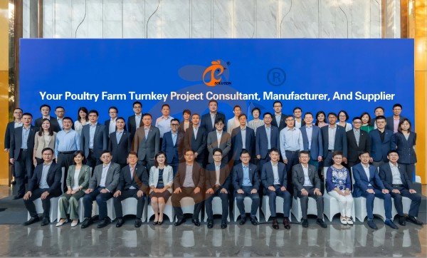
Hong Kong Headquarter Management Team
Hong Kong Headquarter Taiyu Industrial Group CO., LTD
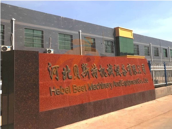
China Hebei Best Machinery And Equipment CO., LTD
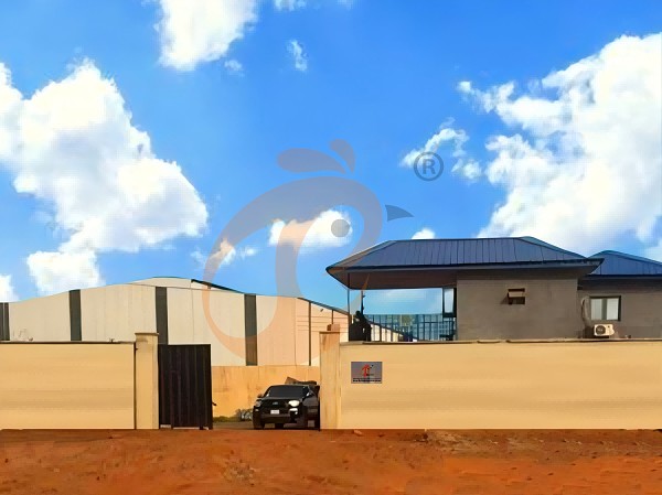
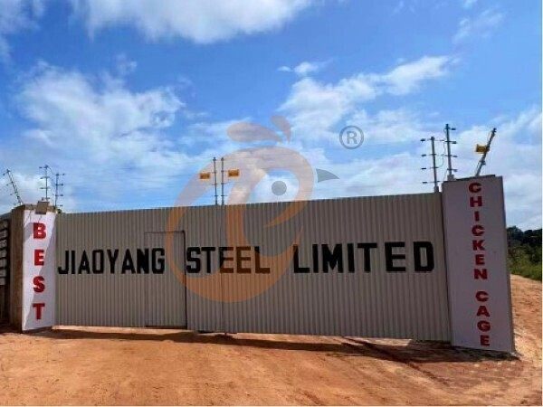
Nigeria Vanke Machinery And Equipment CO., LTD
Tanzania Best Machinery And Equipment CO., LTD
Ethiopia Best Hebei Machinery Manufacturing PLC
Reception /24 WhatsApp NO. : +8618830120193
FAQ
What Maintenance Intervals Are Required For Poultry Manure Removal Equipment?
Lubrication of drive components every 200 hours reduces mechanical wear rates by 30–45%, extending gearbox lifespan beyond 15,000 operational hours under continuous poultry house conditions.
Full system inspection every 30 days identifies corrosion levels under 5% surface degradation, ensuring structural integrity in high humidity environments exceeding 70% relative humidity.
What Are The Environmental Benefits Of Efficient Manure Hygiene Equipment In Poultry Farms?
Dry matter recovery rates increase to 65–75%, enabling manure reuse as fertilizer with nutrient retention of 2.5–3.5% nitrogen content in processed poultry waste streams.
Greenhouse gas emissions decrease by 20–35% through reduced anaerobic decomposition, lowering methane output from manure storage areas across farms managing over 50,000 chickens.
What Is The Optimal Belt Width For Manure Removal Systems In Poultry Chicken Houses?
Wider belts above 100 cm reduce overflow risk by 25–30%, ensuring stable transport in multi-tier cage systems exceeding 4 vertical levels.
Material thickness of 1.2–2.0 mm enhances tensile strength up to 1800 N/m, maintaining durability across 10,000–12,000 operating cycles annually.
Message
Products recommended
 >30,000 Pullets Automatic H Type Battery Cage1. More than 30,000 pullets a house, choose it.
2. It is designed to rearing older than 1 day old pullets to 12 to 16 weeks old chicken starting laying eggs.
3. Its lifespan is more than 25 years.
4. Its structure are Vcloud artificial intelligent fusion, electric control cabinet, automatic equipment of drinking, feeding, manure clean, manual harvesting.
5. Our 24 hour online reception What’sApp NO. is +8618830120193 <30,000 Pullets Automatic A Type Battery Cage1. 10,000 to 30,000 pullets a house, choose it.
2. It is designed to rearing older than 1 day old pullets to 12 to 16 weeks old chicken starting laying eggs.
3. Its lifespan is more than 25 years.
4. Its structure are Vcloud artificial intelligent fusion, electric control cabinet, automatic equipment of drinking, feeding, manure clean, manual harvesting.
5. Our 24 hour online reception What’sApp NO. is +86 18830120193. >30,000 Broilers Semi-Automatic Harvest H Type Battery Cage1. More than 30,000 broilers a house, choose it.
2. It is designed to rearing 1 to 45 day old adult broiler ready for market.
3. Its lifespan is more than 20 years.
4. Our 24 hour online reception What’sApp NO. is +8618830120193, +234 8111199996. >30,000 Broilers Manual Harvest H Type Battery Cage1. More than 30,000 broilers a house, choose it.
2. It is designed to rearing 1 to 45 day old adult broiler ready for market.
3. Its lifespan is more than 20 years.
4. Its structure are Vcloud artificial intelligent fusion, electric control cabinet, automatic equipment of drinking, feeding and manure clean, manual harvesting.
5. Our 24 hour online reception What’sApp NO. is +8618830120193, +234 8111199996. <30,000 Broilers Manual Harvest A Type Battery Cage1. Less 30,000 broilers a house, choose it.
2. It is designed to rearing 1 to 45 day old adult broiler ready for market.
3. Its lifespan is more than 20 years.
4. Its structure are Vcloud artificial intelligent fusion, electric control cabinet, automatic equipment of drinking, feeding and manure clean, manual harvesting.
5. Our 24 hour online reception What’sApp NO. is +8618830120193, +234 8111199996. HK Headquarter Offers EU-standard Poultry Farm Solutions, Manufacture Poultry Farm Equipment1. Continuous communication with the EU and the US
2. China, Nigeria, Ethiopia, Tanzania branch companies and factories
3. The products’ quality is customized for local poultry farms
4. Poultry cage and poultry farm equipment stock for sale
5. 24 online reception Whatsapp NO. : +8618830120193,contact us to get full information China Branch Offer Poultry Farm Business Plan, Manufacture Poultry Farm Equipment1. Address: Flat/RM 2416, 24/F, Runxing Building, Youyi Nan Street, Shijiazhuang City, Hebei Province, China
2. Poultry cage and poultry farm equipment factory and stock for sale
3. Customized for local poultry farms
4. Quality and design are based on Euro
5. 24 online reception Whatsapp NO. : +8618830120193 Nigeria Branch Offer Poultry Farm Business Plan, Manufacture Poultry Farm Equipment1. Address: After Sinoma Office, 200 Meters Near Danco Filling Station, Lagos/Ibadan Expressway, Lagos State, Nigeria
2. Poultry cage and poultry farm equipment factory and stock for sale
3. Customized for Nigerian poultry farms
4. Quality and design are based on Euro
5. 24 online reception Whatsapp NO. : +8618830120193 Ethiopia Branch Offer Poultry Farm Business Plan, Manufacture Poultry Farm Equipment1. Address: WR93+FQ2, Addis Ababa, Ethiopia
2. Poultry cage and poultry farm equipment stock for sale
3. Customized for Ethiopian poultry farms
4. Quality and design are based on Euro
5. 24 online reception Whatsapp NO. : +8618830120193, contact us to get price list Tanzania Branch Offer Poultry Farm Business Plan, Manufacture Poultry Farm Equipment1. Address: No.8, Sova Road, Msufini, Mlandizi, Kibaha, Pwani, Tanzania
2. Poultry cage and poultry farm equipment factory and stock for sale
3. Customized for Tanzanian poultry farms
4. Quality and design are based on Euro
5. 24 online reception Whatsapp NO. : +8618830120193


Contact
By clicking 'Allow All', you agree to the storage of cookies on your device to enhance site navigation, analyze site usage and assist with our marketing efforts.